*Setup instructions are still a work in progress, it will updated as more features are added.*
Remote Specifications
iRemote is an advanced and reliable smart remote for Vesc based ESCs. Bellow is a summary of it’s main components:
Specifications:
- 1 : 240×240 Wide view angle, full color IPS display.
- 2 : Illuminated tactile Power button
- 3 : Hall Effect thumbwheel throttle. ± 45 degrees of precise control.
- 4 : Programmable secondary momentary button
- 5 : Magnetic charging port – Recommended to use ~1A charger
- 6: Factory Reset Button: Located on the back side of the PCB, pressing this button for 5 seconds during boot time will erase all partitions, data, and resets your remote to factory software. *Do not use it unless instructed to do so*
Hardware specifications:
- 3D accelerometer and 3D gyroscope, Haptic motor driver, Linear Bipolar Hall Effect sensor, Lipo battery management IC, 1000mah lipo battery, Soft power latching, Piezo buzzer, ESP32 Wrover with external antenna.
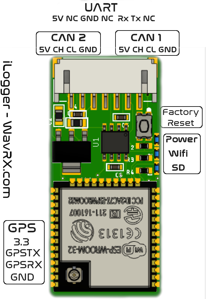
iLogger Pinout / Specifications
iLogger is an all in one logging solution for Vesc based ESCs. It has a compact design and supports both CAN and UART protocols.
Hardware specifications:
- 2x CAN ports : CAN1 and CAN2. CAN1 connects to CAN port on Vesc, while CAN2 is used to forward CANL and CANH pins to the next node.
- 1x UART port
- 1x GPS port: Connects to most GPS based modules and allows location based logging as well as automatic time synchronization.(9600 Baud Rate)
- 1x Micro SD card slot: Accepts up to 32GB formatted as FAT32.
- Orange LED: Power indicator
- GREEN LED: WIFI indicator
- BLUE LED: SD Card mount indicator
- Reset button: Used when upgrading firmware from an SD card, see bellow on how to update.
Requirements
Before using your iLogger, download the infinity tool app from either Google Play store or iOS test flight:
Google Play Download | iOS App Download
![]()
![]()
- Format your Micro SD as FAT32.
- *Always insert or remove SD Card when iLogger is powered off*
- If using CAN, enable CAN Status Message Mode and set it to CAN_STATUS_1. Set CAN baud rate to CAN_BAUD_500K. Set CAN Status rate to 5Hz. Apply those settings to both Vescs.
- If using UART, enable UART app and set baud rate to 115200
Powering Up
IMPORTANT NOTE: USE ONLY ONE PORT AT A TIME. DO NOT CONNECT BOTH CAN AND UART AS THIS WILL DAMAGE YOUR ILOGGER AND OR YOUR ESC.
- If connecting through CAN:
- Plug provided CAN cable into CAN1 port and to your CAN port on your ESC. If you have a dual Vesc they are already connected internally. If you have separate units, use the provided CANL/CANH cable and forward from CAN2 port on iLogger to second Vesc.
- Power on Vesc, iLogger orange LED should light up.
- If connecting through UART:
- Plug provided UART cable into UART port of iLogger and to your UART port on “Master” ESC.
- If running a Dual Vesc, make sure to plug iLogger to UART port of the Master Vesc, and specify Slave ID on the iLogger settings. Plugging iLogger to Slave Vesc won’t be able to correctly detect devices.
- Double check that Tx and Rx pins are correct. Tx pin should go into Rx pin of Vesc, while Rx pin goes into Tx pin. On some Vesc models those are swapped.
- Power on Vesc, iLogger orange LED should light up.
- If a GPS module is available
- Connect GPS to the GPS port and double check that pinout is correct. GPS modules that we sell are tested and have the correct pinout out of the box.
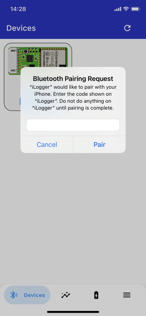
BLE Pairing
Each iLogger module comes with a unique 6 digits pin. If you have lost yours, please contact us at support@wavrx.com with your order # number to assist you retrieving it.
How to pair BLE:
- Power on iLogger, open iTool app.
- Wait a few seconds until device appears under Devices tab
- Tap on “Connect”. A dialogue will popup to let you enter your 6 digit pin.
- After entering your pin, wait a few seconds for the pairing process to finish.
Troubleshooting:
- There are no prompt notifying you if you enter the pin wrong. If you are having trouble connecting to the module its most likely because of a mistyped pin number. Close the app and restart iLogger, then try again.
- If the pairing prompt didn’t popup automatically on first connect, go to your Bluetooth devices menu, find iLogger and pair with it manually, then start the app.

Update Firmware
It is very crucial to keep both app and iLogger firmware up to date as new fixes and improvements are regularly added.
There are two ways to update the firmware on iLogger:
- OTA (Over The Air Updates)
- Manually using SD Card.
Using OTA:
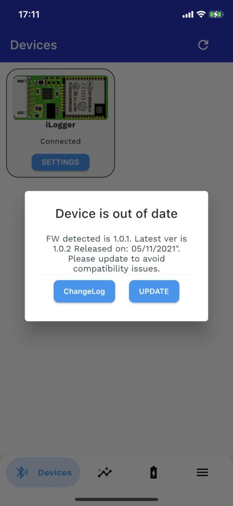
- Once you connect to the module through iTool app, a pop up dialog will notify you if a new firmware update is available.
- Note: If you have ESPNow enable for use with the iRemote, disable it first, apply settings, wait for iLogger to reboot, then proceed with the update. This is necessary to enable Wifi access on iLogger. Once finished, enable it back on and apply settings.
- Otherwise, tap on settings, Update, then OTA process will check if a new version is available. If an update is available, it will start automatically and will last between 2-5 minutes to finish. Do not interrupt or power off during that time.
- A confirmation dialog will popup if the update was successful and iLogger will automatically reboot, otherwise, an error message will appear explaining why.
Using SD Card:
- Download and place update.bin firmware at the root of an SD Card.
- Insert SD Card while iLogger is powered Off.
- Hold reset button and turn ON ilogger.
- Keep holding for 3 seconds then release reset button.
- Blue LED will start flashing rapidly indicating firmware is being updated.
- Do not interrupt, iLogger will automatically reboot after the update is done.
Configuration Setup
To get started logging Vesc data, and assuming your device is already paired with the iTool app, Tap on “Connect”, wait 3 seconds to initialize and read all BLE characteristics, then tap “Settings”
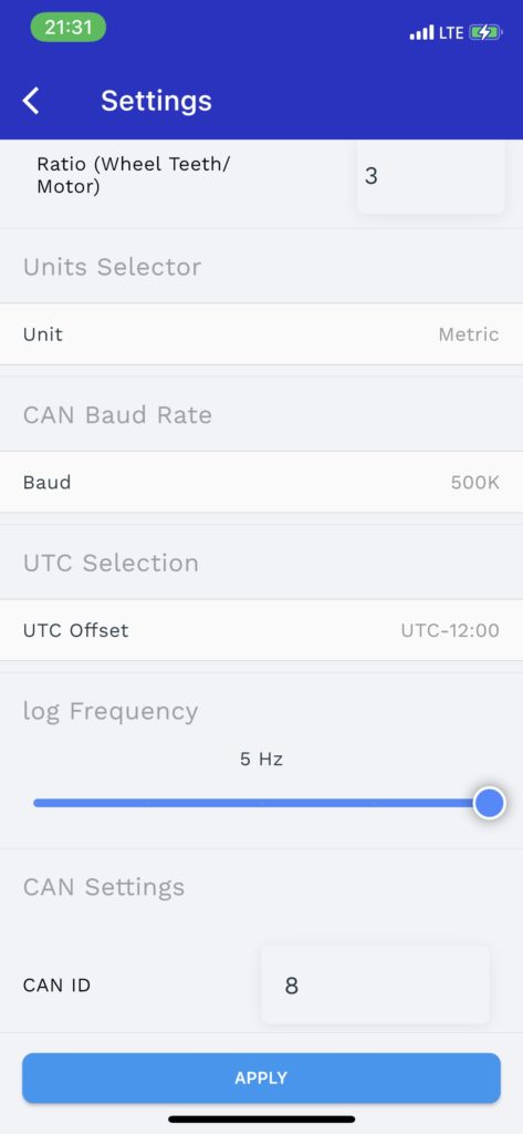
All device configuration is done under “Settings” tab:
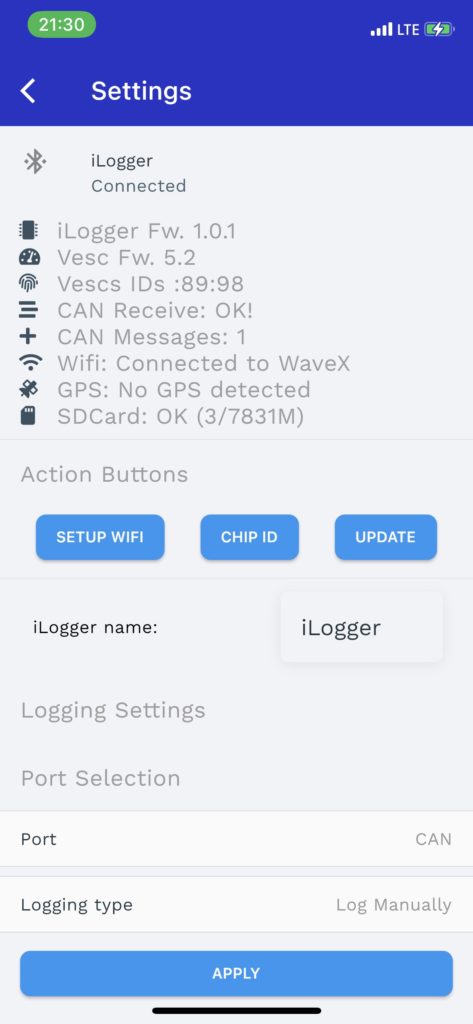
Overal Status values:
- BLE connection status: Should display “Connected”.
- iLogger Fw: Displays current firmware ver. of the module
- Vesc Fw: Displays detected Vesc firmware version
- Vescs IDs: If multiple Vescs are detected through CAN, their IDs will be displayed here.
- CAN Receive: Displays CAN communication status.
- CAN Messages: Displays 1 if iLogger has been able to receive CAN message from Vesc.
- Wifi: Displays Wifi status along with SSID if connected.
- GPS: displays GPS status.
- SDCard: Displays SD Card status and used/total capacity if mounted successfully.
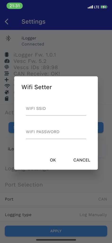
Setup Wifi Button:
Tap on setup wifi and enter access point SSID and password (Note: Only 2.5Ghz networks are supported, 5Ghz won’t connect). If no password is required, leave empty. Tap on Ok. Module will auto restart and attempt to connect to WIFI.
If connected successfully Green LED will lit up.
Wifi is used for OTA updates, time and date synchronization and uploading logs to online account.
Chip ID Button:
Chip ID button display your unique hardware Chip ID. Keep this ID private as it is used to register your device on the online dashboard account.
Update Button:
Performs an online version check and starts OTA if a new firmware is available. Module should be connected to WIFI.
iLogger name: Can be used to customize a unique name for the device.
Port: < CAN – UART >: Used to select either CAN or UART communication.
Logging Type: <Log Manually – Log on Power ON – Log After Elapsed Time>: Three possible logging modes can be selected.
- Log manually: doesn’t start logging unless the “Start Logging” button is tapped, and doesn’t stop logging until “Stop Logging” button is tapped.
- Log After Elapsed Time: Starts logging automatically on Power ON after a specified delay in Seconds.
- Log on Power ON: Starts logging automatically on Power ON without delay.
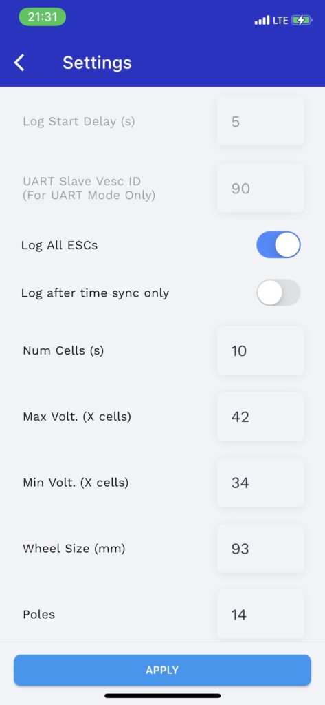
Log Start Delay (s): When Log after delay is selected, logging automatically starts after specified delay in seconds.
UART Slave Vesc ID: When UART is used, specify slave vesc ID to allow dual VESC logging.
Log All ESCs: <On – Off> Logs all detected Vescs simultaneously or only the master unit. When using CAN, iLoggers attempts to detects and Logs all Vescs on CAN network. When using UART, both master and slave Vescs are logged.
Log after time sync only: <On – Off> When toggled on, starts logging only after time has been synchronized automatically through Wifi or GPS lock.
Num Cells: Sets the number of battery cells.
Max Volt.(v) The maximum battery pack voltage (eg. 42).
Min Volt.(v) The minimum battery pack voltage (eg. 34).
Wheel size (mm): When size in mm. Used to calculate speed and traveled distance.
Poles: Number of motor poles (eg. 14)
Ratio (Wheel Teeth/Motor Teeth) : Gear ratio (eg. 3)
Units: <Metric – Imperial>: Converts telemetry between Metric or Imperial calculations.
CAN Baud Rate <50K – 125K – 250K – 500K – 1M>: Defaults to 500K.
UTC Offset: Sets correct UTC Offset for proper time synchronization.
Log frequency: iLogger automatically adjusts logging frequency when multiple Vescs are detected. It is highly recommended to leave it at 5Hz.
CAN ID: Sets iLogger own CAN ID, recommended to keep it set to 8.
BMS CAN ID: Sets the CAN ID of DiebieMS or similar. (Default 10).
Apply: After making any changes to settings, tap Apply and wait for iLogger to automatically reboot for changes to take effect.
Real-Time Telemetry
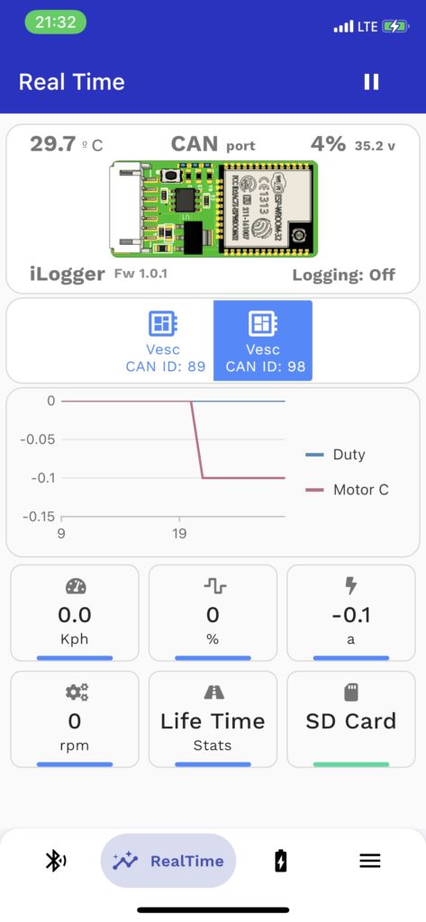
Real time tab allows you to see real time data flow from iLogger.
Different displayed data are:
- ESC temperature
- Used port
- Battery voltage and percentage
- Logging status
- Detected Vesc IDs
- Duty and Motor current real time charts
- Speed – Duty – Motor current – RPM – Life Time recorded stats – SD Card
Life Time Stats
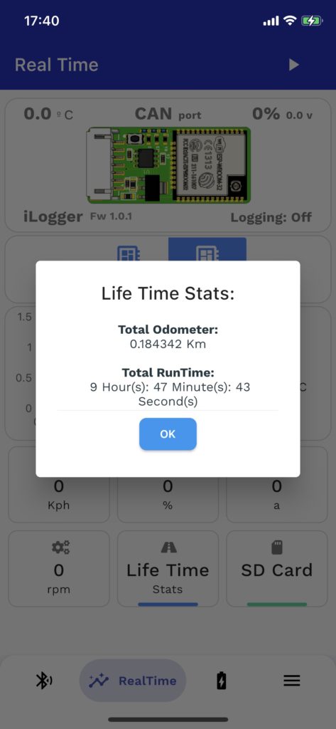
Life Time Stats:
Life time data is recorded on SD Card under file name LT.Dat. Make sure to not delete or modify that file.
Currently recorded life time stats are total odometer ( traveled distance) and total run time.
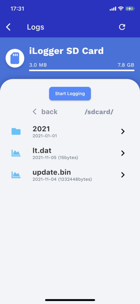
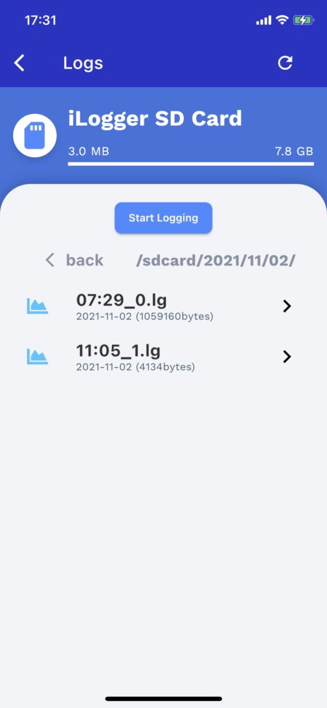
SD Card Browser
iTool app allows you to browse SD card over BLE.
To access SD Card, open RealTime tab and tap SD Card.
Logs are stored as:
- Year Folder
- Month Folder
- Day Folder
- Record time.lg
- Day Folder
- Month Folder
If logging manually, you can start and stop logging from the SD card tab.
Viewing a log:
There are two ways you can view a recorded log:
- Streaming over BLE from iTool app:
- Uploading to online cloud viewer.
1.Streaming over BLE:
Find a log by browsing through the Year/Month/Day/ folders.
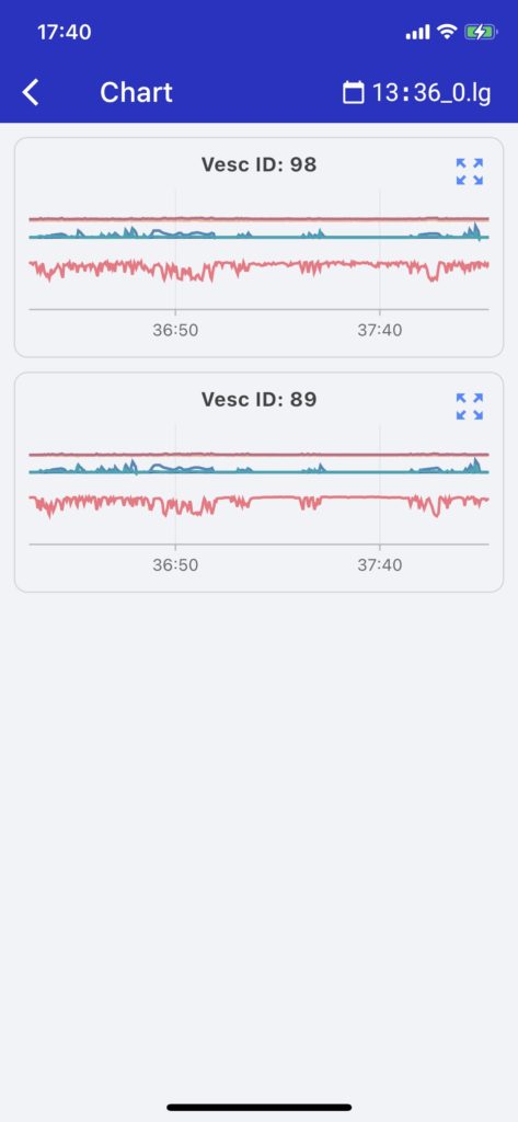
Tap on a log, then select “VIEW”.
After the file is streamed, a Chart view will appear with all recorded Vesc data if available.
Each record has an expand button, which displays telemetry data in a more detailed view.
2.Uploading to online cloud viewer:
Tap on “Upload”. Log will start uploading automatically. When done, you will be given a generated unique URL that you can use and open on any browser for a more detailed and faster chart viewing. Uploaded logs are saved on the cloud and accessible from your online dashboard account
Exporting logs:
Online view allows you export logs in different formats.
Supported export formats are:
- PNG, JPEG, SVG, PDF
- JSON, CSV, XLSX, HTML
Delete a record from the SD card:
Swipe on any record to delete. A confirmation dialog will appear to confirm.

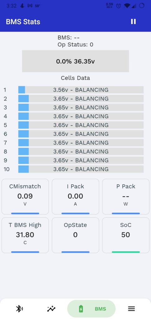
BMS Tab
iLogger has the ability to detect and read data from DieBieMS based BMSs through CAN Bus.
Real time data is displayed including:
- Different cells voltages
- Status
- Pack voltage
- Current
- Temperature
- State Of Charge
Support for LLT is coming up soon.
Get Started
Powering up:
Short press the power button once.
Powering down:
Long press the power button.
Vesc Control Over CAN BUS:
The remote only works over CAN BUS to provide the most optimal and safe control operation. Your iLogger has to be connected to a CAN BUS port on your Vesc, and configured to use CAN BUS.
CAN Bus offers an extremely reliable and safe communication compared to UART, it does also allow a seamless and instantaneous multi-vesc control.
iLogger comes configured to use CAN Bus port by default.
Set the following on All Vescs:
- Set Can Status Message Mode to CAN_STATUS_1
- Set Can Status Rate to 5Hz
- Set CAN Baud Rate to CAN_BAUD_500K
Connecting iLogger to CAN BUS:
Please refer to iLogger setup guide for complete pinout.
Use provided 4 wire CAN cable and plug iLogger to your Vesc CAN port. Pinout of the cable are +5V CANH CANL GND.
On most Vesc variants, it should work right away, however, a slight modification is need for Stormcore ESCs.
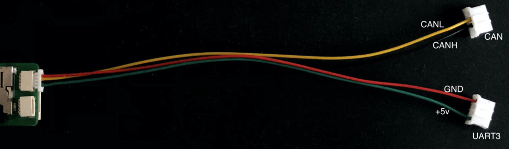
Stormcore setup:
iLogger won’t be properly powered up if connected directly to CAN port on Stormcore. A workaround is to make a Y-Split CAN cable from the provide two CAN cables.
The Y-Split cable have one head connecting to CAN port (CANH and CANL), while the other head connects to UART3 port (+5v and GND).
Y-Split cable: cables are not color coded, double check pinout
Control Modes:
iRemote has two control modes : “Direct” and “Vesc App”.
Control modes can be changed from a dropdown menu under Settings – Parameters.
“Direct” Control mode: This mode offers the most direct and instanteneous control over your Vesc. It uses direct current control commands to all motors on CAN bus bypassing any ramping values.
“Vesc App” Control mode: This mode switches over to the Vesc remote app on Vesc tool. Using this mode unlocks Smart Reverse, and control is governed by the ramping and settings adjustable from the Vesc Tool under “App Settings” – “Vesc Remote”
Important:
For “Vesc App” control, make sure to have the following on your Vesc tool for both vescs:
Under “App Setting” – “Vesc Remote” – “Control Type” set to “Current” and “Input Deadband” set to “0%” because deadband is controlled from the built in remote setting.
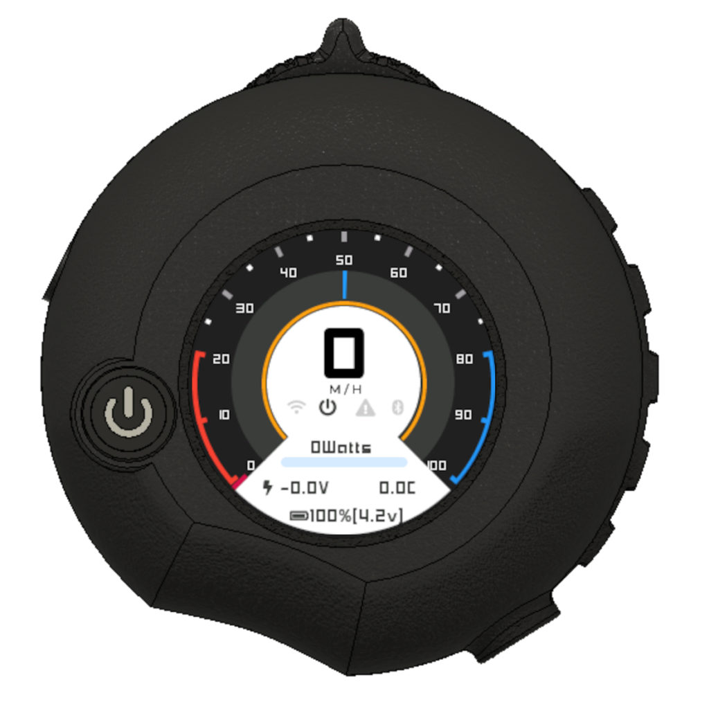
Main Menu:
Short press the power button two times to access the main menu.
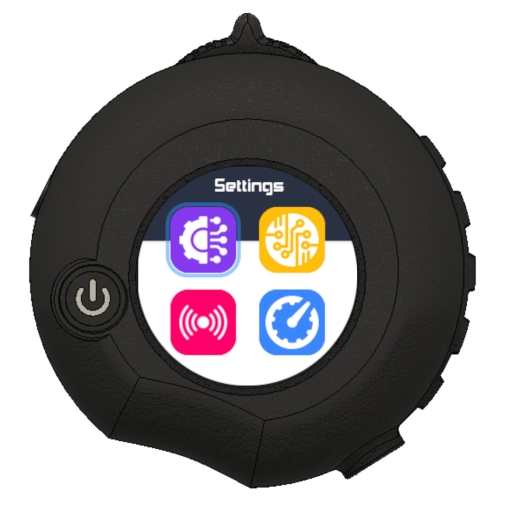
Main Menu options:
- Settings: Access secondary settings menu where most of the system adjustments can be made.
- SysInfo: Access real time system information about the remote.
- Pair: Access pairing settings
- Back: Return to main odometer screen
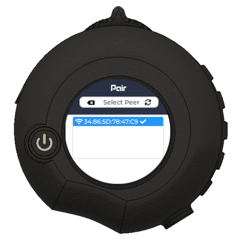
Pair Screen:
Pairing screen allows you to see a list of paired iLoggers.
Note: If you purchased an iLogger module along with your iRemote, it should come already pre-paired.
If an iLogger is already paired with your remote, it will be listed on the Pair screen.
If not, iRemote will automatically enter scanning mode, waiting for an iLogger response.
How to pair an iLogger:
If no device is previously paired:
-
- Enter the Pair screen
- A scanning message will appear, along with a loading animation
- Turn on iLogger and wait for 5 seconds.
- Press the tiny momentary button on iLogger once
- A confirmation message will appear on the remote, showing that it was paired successfully.
- Press OK and it should be ready to go.
If an old device was already paired and you want to start the process again:
-
- Enter the Pair screen
- Click on the iLogger you want to un-pair
- A confirmation dialog will popup
- After un-pairing, perform the pairing procedure described above.
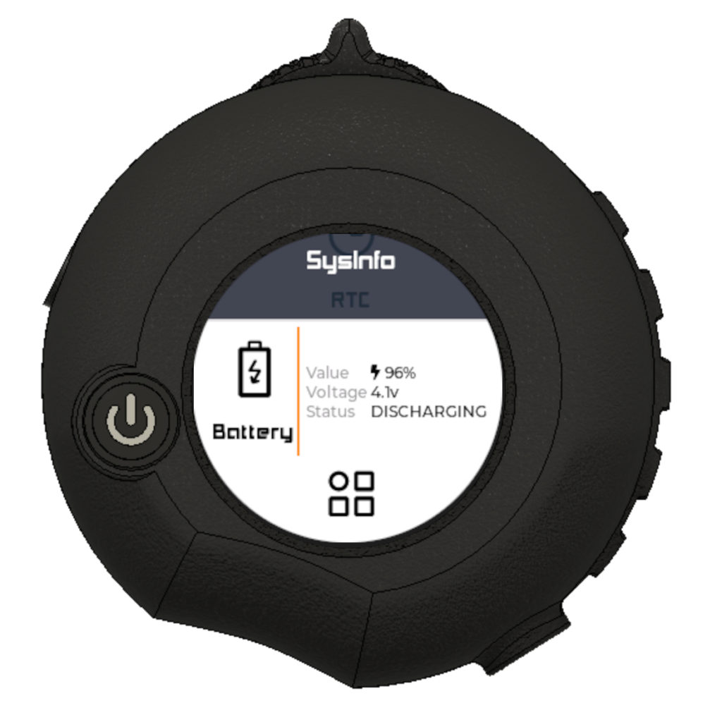
SysInfo Screen:
This screen displays various real-time remote system information.
-
-
iLogger
- iLG Fw: Displays paired iLogger firmware version – This is retrieved on first power up only.
- Link: Percentage of data rate between iRemote and iLogger. 100% means excellent connection quality with no packets drop.
- AFH: Adaptive Frequency Hopping counter, this number shows how many times the system had to hop between different frequencies to avoid interference. 0 means no interference detected thus far, and therefore the system didn’t have to change frequency.
- Missed: Displays the number of missed packets.
- Port: Shows which port iLogger is configured to use.
- CAN Bus: Show CAN bus status
-
-
-
IMU
- Ax : Accelerometer x-axis value
- Ay: Accelerometer y-axis value
- Az: Accelerometer z-axis value
- Gx: Gyroscope x-axis value
- Gy: Gyroscope y-axis value
- Gz: Gyroscope z-axis value
-
-
-
RTC
- Date: Current system date – This date is currently not synchronized
- Time: Current system time – This time is currently not synchronized
-
-
-
Battery
- Value: Percentage value of iRemote Lipo battery. 100% means fully charged.
- Voltage: Real time voltage reading of the Lipo battery
- Status: Real time battery status
- DISCHARGING: Battery in use when no external power is applied.
- CHARGING: When external power is connected, battery is in charging state.
-
-
-
Sys
- FW: iRemote firmware version
- HW: iRemote hardware version
- Heap: Current free memory size, and the lowest recorded free memory since system boot.
- Flash: Onboard flash size (Even tho some remotes have a 16MB flash size, this will show as 8MB due to the pay partitions are laid out.)
- By: wavrx.com
- Reset: Displays the last system reset reason, useful to know when your remote unexpectedly rebooted.
-
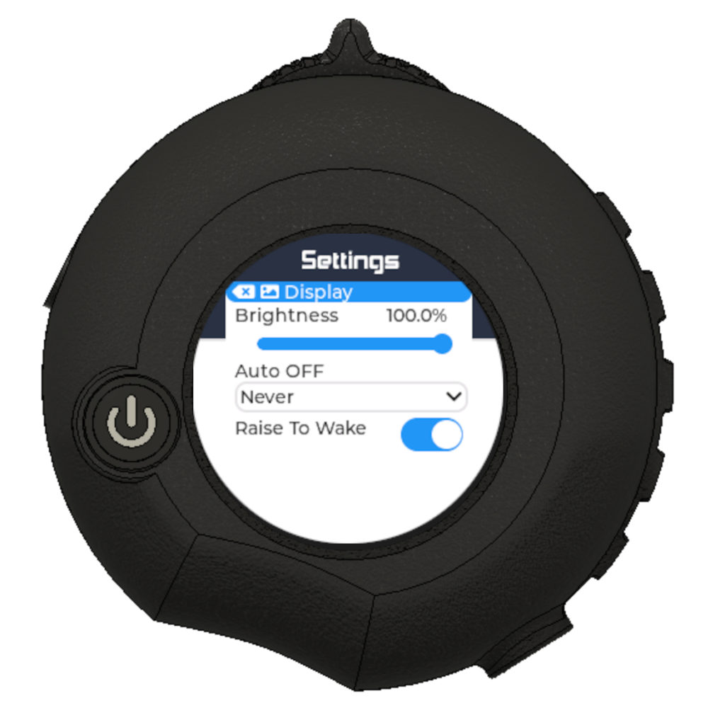
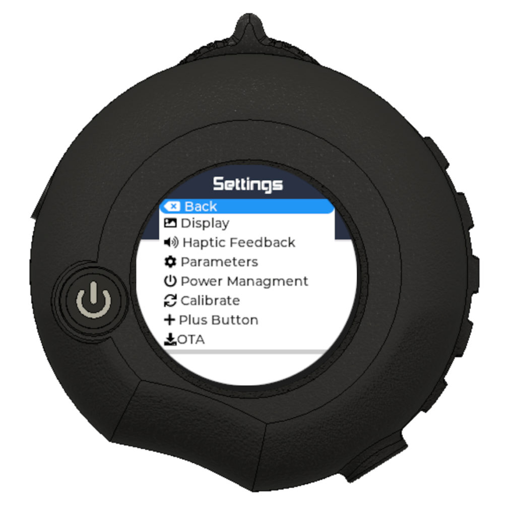
Settings Menu:
- Display
- Brightness : Slider that controls the brightness of the display. 100% means full brightness.
- Auto OFF: Drop down menu to set the auto display OFF timer.
- 10 Seconds, 30 seconds, 60 seconds (Default) or Never.
- Raise To Wake: Default to ON. Toggles Raise To Wake feature On/OFF. Recommended to keep it ON to save power when not looking at the screen.
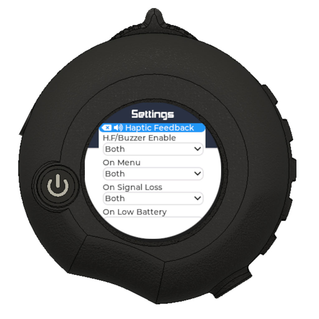
- Haptic Feedback
- H.F/Buzzer Enable : Drop down menu to enable Haptic Feedback, buzzer, both, or Off.
- On Menu: Drop down menu to control H.F/Buzzer notifications on menu changes
- On Signal Loss: Drop down menu to control H.F/Buzzer notifications on signal loss
- On Low Battery: Drop down menu to control H.F/Buzzer notifications on remote low battery
- On Faults: Drop down menu to control H.F/Buzzer notifications on Faults
- Parameters
- Adaptive F.H: Toggle button to enable/disable Adaptive Frequency Hopping. (Default ON).
- Wheel Size
- Gear Ratio
- Motor Poles
- Cells
- Metric: Toggles metric units On/Off
- Power management
- Auto Power OFF: Toggles automatic power OFF. It is highly recommended to leave this option turned ON. This settings allows your remote to automatically shutdown when left unattended for a specified time period.
- Idle Timeout: Slider to set a time period in minutes before the remote is automatically powered down when not in use.
- Calibrate
- DeadBand: Sets the thumbwheel deadband before engaging. Recommended to keep value set at 150.
- Start Hall Calibration: This menu will take you to the calibration screen (See How to Calibrate section).
- Plus Button
- Function: Drop down menu to program the Plus button.
- Ch1 Toggle: Sets the button as a toggle to the digital channel 1 on iLogger. Hold for 3 seconds to toggle On/OFF
- Ch1 Hold: Sets the button as a momentary digital channel 1 toggle. Keeps pressing for ON, release for OFF.
- Safety Hold: Sets the button as a safety switch. Hold to unlock thumbwheel throttle, release to lock input.
- Safety Toggle: Sets the button as a safety switch. Hold for 3 seconds to lock throttle, hold for 3 seconds to unlock.
- Function: Drop down menu to program the Plus button.
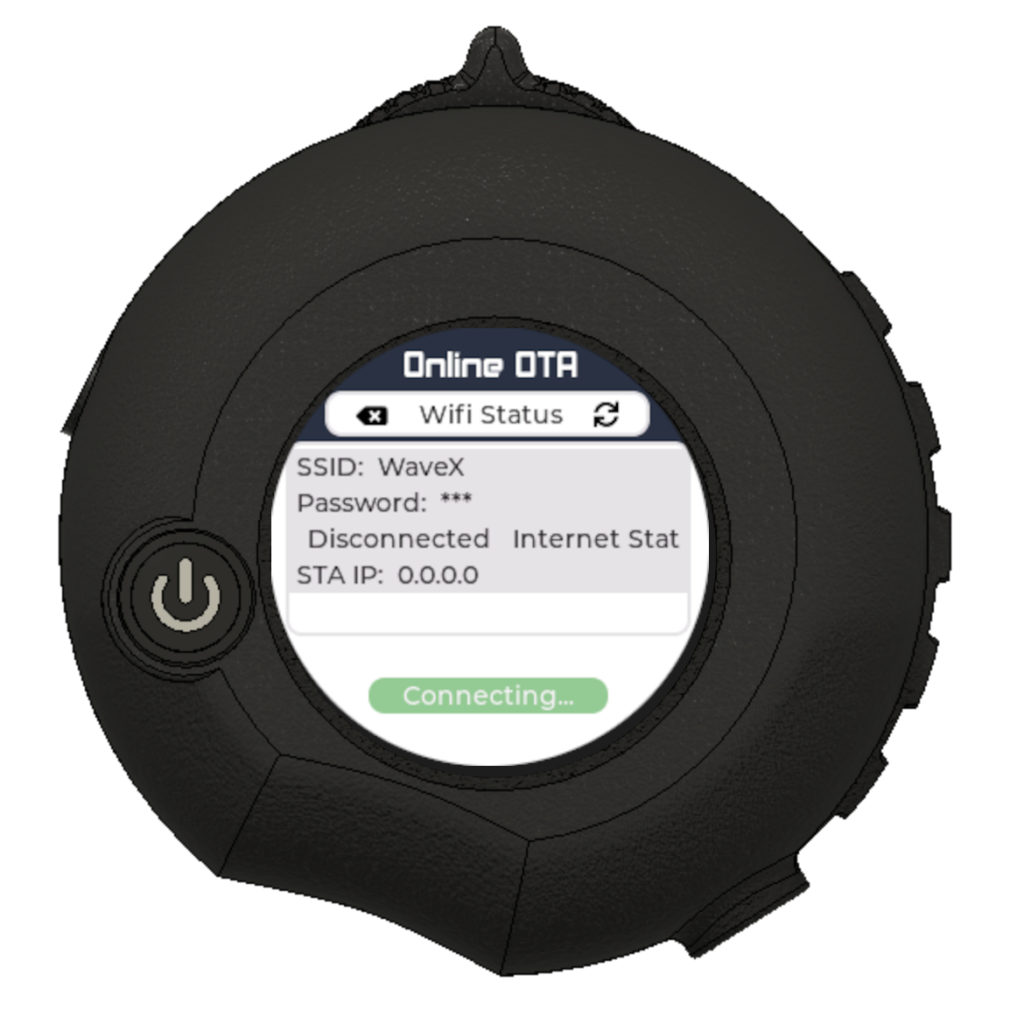
- OTA
- Online – OTA: This option will take you to the Over-The-Air screen. (See OTA section)
- Core Dump Report: This option will take you to the core dump reporting screen where you can automatically send crash reports. (See Core Dump Report section)
How to connect iRemote to Wifi
In order to perform OTA updates or send bug reports, the remote has to be connected to the internet through Wifi.
To make this process as easy as possible, the remote automatically retrieves your Wifi credentials from the iLogger upon first boot, they are then stored internally.
You can set your Wifi credentials on iLogger through the iTool app, or by simply modifying the JSON file located at the root of your SD card found inside the config folder.
How to Calibrate Hall Effect Thumbwheel
Remotes are pre-calibrated, however sometimes it might be necessary to re-calibrate hall effect thumbwheel if some parts are changed.
To start the calibration process:
- Go to main menu by pressing the power button.
- Go to Settings menu
- Go to Calibrate menu
- Scroll down to “Start Hall Calibration”
- Slowly move the thumbwheel all the way to the left
- Slowly move the thumbwheel all the way to the right
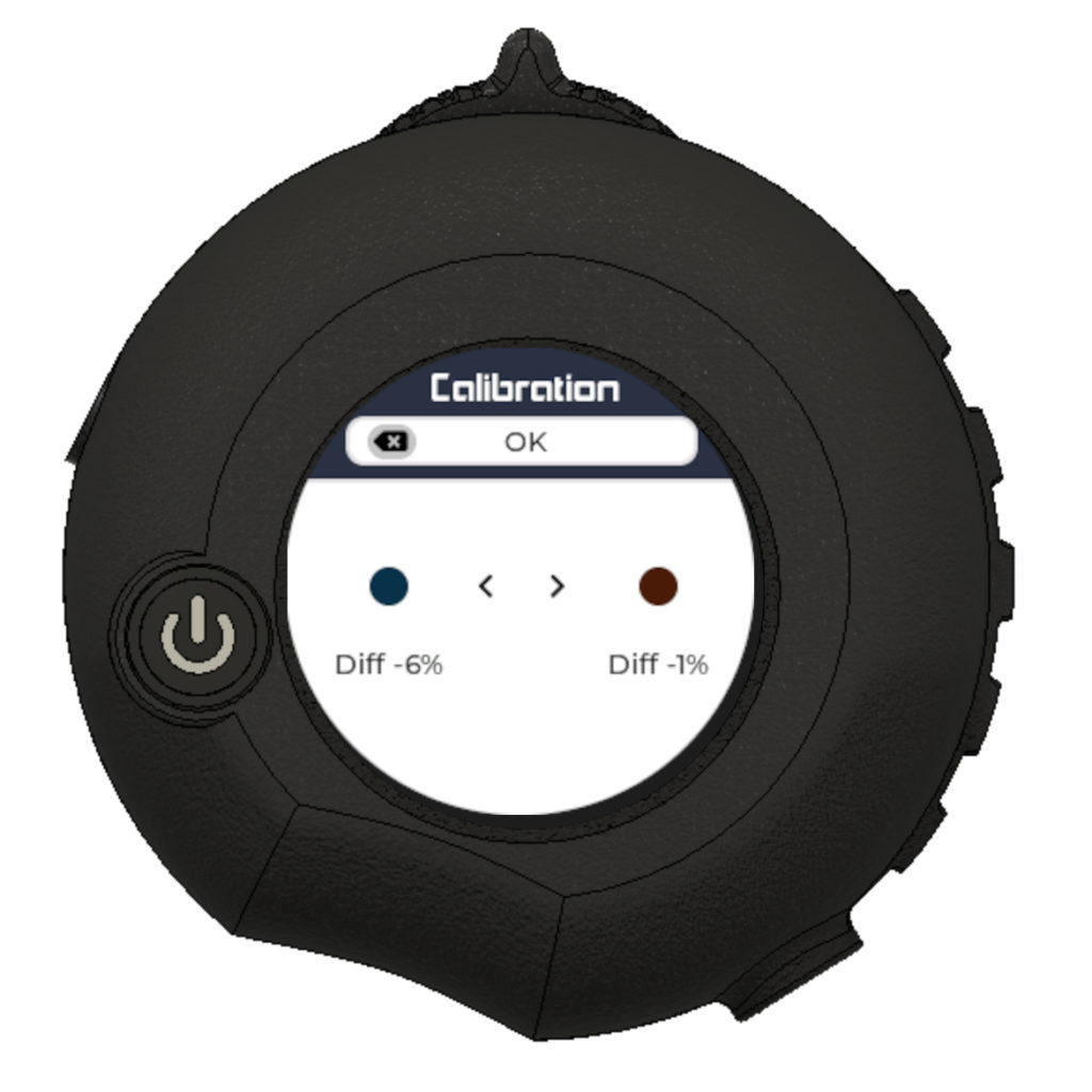
- An “OK” status message should show on top of screen
- Press power button once to confirm changes
Note: On Calibration screen, there are two Diff. values. These values show you the difference in percentage between the old calibration value vs the new one. Ideally these values should be less than 20% for calibration to succeed.
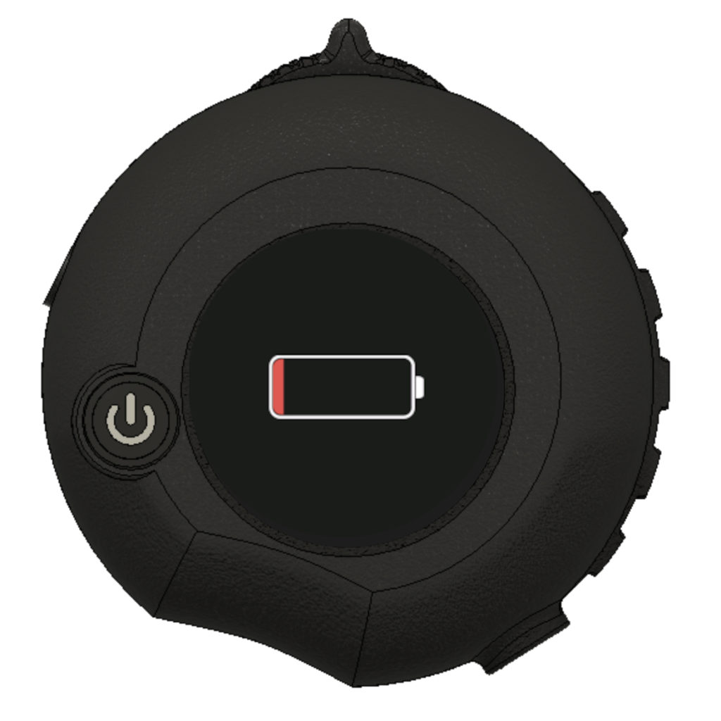
Low Battery Screen
When powering up and the remote battery is detected to be deeply discharged with its voltage dropping below the minimum operating requirements, a low battery screen will be displayed instead of a normal boot.
During this mode, the remote will automatically shutdown after 5 seconds of displaying the notification.
To solve this, plug your remote to USB and let it charge.